Flow
UPDATE, 6/1/07: Make sure you take a look at the comments to this post. There's more information there.
Each pump at the floodgates has a flowmeter on it which measures the flowrate of water through the pump units. The meters are ultrasonic units manufactured by Endress+Hauser. Specifically, they are model Prosonic 93W meters. What that means is that the transmitter (the box with all the electronic guts and the display) is a Prosonic 93. The "W" refers to the type of sensor. Endress+Hauser's flowmeter page is here. At that link, the specific page for the Prosonic 93W can be found by clicking on the box corresponding to "Ultrasonic Flowmeters" and "Conductive Liquids". Then, along the left hand side, you will find a menu entry for "Prosonic Flow 90W, 93W." Here's a picture taken from the Prosonic 93W page:

The way these things work is pretty simple. One of the sensors (the two little cylindrical things on the left in the picture, and which are about the size of a small can of tomato paste) is clamped to the outside of the pipe. It sends an ultrasonic waveform out through the pipe and the water flowing through the pipe. That signal is picked up by the other sensor, clamped to the outside of the pipe 180 degrees opposite to the first sensor. The other sensor sends the signal to the transmitter box (the blue and white box in the picture above, which is actually a model 90 transmitter - the model 93 has a bigger display and more plugs on the bottom) for processing. Depending upon how the waveform has changed as it has traveled through the water, an average velocity of the water can be calculated. If one wants a more accurate measurement, a second set of sensors can be added and the two signals can be averaged. The floodgates installations use just such a two-channel arrangement. After averaging, the transmitter can then send the flow data to a controls system for display elsewhere. The results are also displayed locally on the transmitter's screen.
It only makes sense that one would want as steady a flow as possible for measurement. Turbulence would scramble the signal, increasing the error in measurement. For this reason, the manufacturer recommends installation of the sensors a specified distance away from anything that could disrupt flow, i.e. introduce turbulence. Such things could be elbows, pumps, valves or pretty much anything other than straight pipe.
The distance is measured in multiples of diameters of the pipe. In the Prosonic 93 installation literature, which can be downloaded from this link, the specified distance downstream from a pump is called out as 20 times the pipe diameter. Here's the applicable picture from page 30 of the manufacturer's manual (which I have annotated in red):
The diameter of the pipe for each individual pump is 60". Those 60" lines - in groups of two or three - flow into 108" (9 foot) pipes that go straight out to the lake.
In the case of the flowmeters on each of the pumps, the sensors are located approximately 1 (one) diameter downstream from the pump. They are mounted pretty much right on top of the pump. Below are a few pictures to show the location of the sensors and transmitters.
Here's a picture of a removed discharge elbow at the Orleans Avenue site. These elbows fasten to the tops of the pumps once the pumps are in their frameworks out in the canal. I've annotated a few details on it. Inside the white box is the location for the sensors.

Below is an enlargement of the area inside the white box above. I've noted the locations for the sensors. As you can see from the photo above and the enlargement, they are only about four or five feet above the flange that bolts to the pump.

In the picture below I've noted the locations of the Prosonic 93 transmitters on the pump platforms.

Below is an enlargement of the transmitter on the left.

The picture below shows the Orleans Ave pumps on the east bank. I've highlighted the area which is enlarged in the next photo.

The picture below shows the highlighted area enlarged from above. As you can see, the flow sensor is just above the discharge of the pump.

In the photo below (an enlargement from another photo) you can see the orange straps on the adjacent pump which hold the sensors in place.
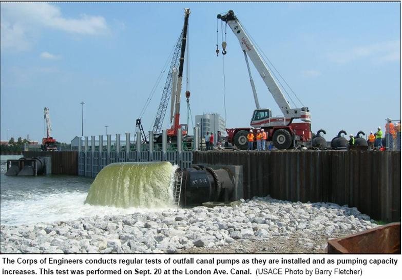
The photo below is taken from a short version of May 25, 2007 AP story about the testing of the Orleans Avenue pumps the previous day. The short version appeared in the Miami Herald, and had three pictures attached to it. The full version is here, sans photos.

On the picture, I've highlighted the bands that hold the sensors with red arrows. Inside the white box, one can see one of the sensors placed at exactly the location it was before the refitting of the pump units with hard pipe and new hydraulic motors.
And in the picture below, a screen capture from a May 15, 2007 WWL-TV report about pump testing at Orleans, you can see that the flow meters are definitely in use. The gentleman on the right appears to be a contractor from Prime Controls, according to the "PRIME" sticker on his hardhat. Prime is the contractor responsible for the entire SCADA system. I'm not sure what agency or company the gentleman on the left is from. But as you can see, they're both checking the flowmeter.

There's two problems related to the flowmeters here, one that may be solvable, and one that needs to have questions asked about it.
The first problem is this... in this installation, the flowmeters are pretty much in the worst possible spot to measure flow because of the highly turbulent nature of the flow immediately downstream of the pump discharges. As such, there is a large error being introduced into the flow measurement. In a perfect installation, the Prosonic 93 with W sensors has about a 0.5% error, which is pretty good. In this installation, which is far from perfect, the error could be significant. I can only guess, but I'm sure the Corps guys running the floodgates project know (at least I hope they do).
Is there a way to solve this? Maybe. There aren't many good spots on the individual pump discharges on which to place these sensors, due to the numerous sources of turbulence. For example, at 17th Street, all of the pumps shoot the water up into elbows, which are themselves bolted to elbows, which are welded to the 9 foot pipes. Thus, the individual discharges for each pump are nothing but sources of turbulence. It would be the worst place in the site to put flowmeters, but that's where they are. Here's a picture of 17th Street from last fall, showing the pump discharges:

Given a choice - and they are admittedly few - the best place to look for a location for the sensors would be on the straightest piece of pipe possible, as far away from sources of turbulence like the pump discharges or the tees where the 5 foot individual pump lines drop into the 9 foot pipes. The best place, given those parameters, would be on the 9 foot pipes on the lake side of the gates. According to the manufacturer's literature, the "W" type sensors can be placed on a 9 foot pipe and still work just as well. One would not have accurate flowmeter readings from individual pumps, but the existing flowmeters could still be used strictly for indication of flow ("It's flowing, but we don't know if the rate on the display is actually true."). However, one would have a better feel for the overall flow for the set of two or three pumps going into each of those nine foot pipes. Here's a picture of the lakeside location at 17th Street, taken from NPR's May 18th article about what's going on with the pumps:

Here's an overhead shot of 17th Street taken from a May 4, 2007 WWL-TV report, which shows the substantial length of straight pipe available:

The choice at Orleans isn't so great, since the straight section of the 9 foot pipes aren't nearly as long as at 17th Street (picture also taken from the May 18, 2007 NPR article):

As you can see, there are no sensors currently strapped to these locations.
London is about the same as Orleans, since it was designed by the same firm - URS (screen capture from April 30, 2007 WWL-TV report, sorry about the quality):

A closer view of the 9 foot pipes can be found in this USACE photo, previously shown in my October 21, 2006 post:

The second problem is more logistical in nature, but no less severe. One might think that the measurement of the flow is merely an academic matter. It's nice to know, but don't we just want to turn the pumps to "11" and let 'em rip? Well normally, yes. But remember that there's not enough pumps at the lakefront to match the what can be put into the canals on 17th Street and London Avenue. In addition, the Safe Water Levels must not be exceeded (By the way, that's going to be real tricky on London Avenue, considering that the pumps were specified to run at around 4 feet above mean lake level, which is also the safe water level on the canal. Modifications to the discharges of the 9 foot pipes have supposedly allowed the pumps to run at a lower height - perhaps 2 or 3 feet, but who knows if that's actually true?).
When one takes both these circumstances - too few floodgate pumps and the Safe Water Levels - into account, it becomes clear that there is a delicate balancing act to be peformed between the New Orleans S&WB pump operators in stations 6 (17th St), 7 (Orleans), 3 and 4 (London Avenue) and the Corps pump operators at each of the gate structures. The way that that balancing act is performed is by relying - in part - upon the readings from the flowmeters, which are piped through the SCADA system to the computer terminals in each pump station (except pump station 4 on London - I assume messages to the operators in that station will be relayed via the folks in station 3).
The Floodgates Operating Manual recognizes this. Here's the section titled "Step 9 (T - 6 hours)" (sorry, but the Corps isn't big on paragraph breaks. This is exactly as it appears in the manual):
A few notes are necessary. First, let me explain the numbers on the "targeted level" in the above paragraph.
The only copy of the manual that has been released is from July of last year. At that time, the Safe Water Level was 5 feet at both 17th Street and London Avenue. Since then, the SWL has changed to 6 feet at 17th Street and 4 feet at London Avenue. Elsewhere in the manual, levels one foot below the safe water level are noted as the activation depths for the floodgate pumps. Thus for London Avenue, the steady flow operating range is probably 2 to 3 feet now, not 3 to 4 feet. And for 17th Street, the range might be 4 to 5 feet, or it might have stayed the same.
Also, the Canal Captains are the Corps Operations representatives in the S&WB pump stations. They'll be huddled over the readouts from the SCADA system, checking the canal depths from the level gauges and the flowmeter readings from the floodgate pumps. As one can see, the flowmeter readings will be part of the data considered by Corps personnel in their decisions to advise S&WB personnel to turn off the city's pumps.
For storms below category 3, Corps personnel are supposed to remain at the floodgates. Supposedly, they'll button themselves up in the little bunkers on the drive platforms, but considering the courage it takes to volunteer for such duty, I seriously doubt they will stay inside if there's a problem or if a request comes over the radio to check a flowmeter out on the pump platforms. Thus, there will likely be a backup for the flow signal received in the S&WB pump stations in the form of Corps Operations person who can look at the local display at the gates, as well as look at the pumps themselves.
Problems arise, however, when the storm is a category 3 or above. In that case, the operators are supposed to evacuate the floodgates. Now, I think it's questionable that they will do so. After all, these guys are probably pretty dedicated, and would most likely have to be escorted off the drive platforms at the point of a gun. I would compare that to the situation exemplified by the S&WB drainage pump operators who stayed during Katrina.
However, sometimes orders are orders, and you must leave. That situation is demonstrated by the evacuation of Jefferson Parish's pump operators during Katrina. With the operators gone, and with no automated system to control or adjust the pumps, the lake backflowed through the JP pump stations into most of the east bank of Jefferson Parish, a totally manmade disaster.
So for truly nasty storms (cat 3 and above), there might be no crews out at the floodgates. In addition (and this is according to the manual) for category 4 or 5 the Corps also pulls the Canal Captains out of the S&WB stations and relocates them to the Corps headquarters on Leake Ave at the river. The S&WB determines whether to leave the S&WB operators in the S&WB stations.
What this means is that all the data to determine whether to turn off more city pumps than will already be turned off (and they will be turned off after the gates drop; otherwise, they'd overwhelm the Corps pumps) will be received via the SCADA system. This includes the data from the flowmeters, which is most likely inaccurate, possibly greatly so.
So two questions need to be asked:
1) Assuming that the use of ultrasonic flowmeters was the correct choice in this application, does the Corps know how accurate the data from those flowmeters actually is? That is, has anyone done detailed baseline tests to determine whether there really is an error due to the current installation position of the pump flowmeters?
2) Does the Corps plan on running drills in which there are no operators interacting with the machinery at the floodgates, in order to determine whether there are kinks which need to be worked out? After all, their plans call for the floodgates to be evacuated in heavy storms.
Each pump at the floodgates has a flowmeter on it which measures the flowrate of water through the pump units. The meters are ultrasonic units manufactured by Endress+Hauser. Specifically, they are model Prosonic 93W meters. What that means is that the transmitter (the box with all the electronic guts and the display) is a Prosonic 93. The "W" refers to the type of sensor. Endress+Hauser's flowmeter page is here. At that link, the specific page for the Prosonic 93W can be found by clicking on the box corresponding to "Ultrasonic Flowmeters" and "Conductive Liquids". Then, along the left hand side, you will find a menu entry for "Prosonic Flow 90W, 93W." Here's a picture taken from the Prosonic 93W page:

The way these things work is pretty simple. One of the sensors (the two little cylindrical things on the left in the picture, and which are about the size of a small can of tomato paste) is clamped to the outside of the pipe. It sends an ultrasonic waveform out through the pipe and the water flowing through the pipe. That signal is picked up by the other sensor, clamped to the outside of the pipe 180 degrees opposite to the first sensor. The other sensor sends the signal to the transmitter box (the blue and white box in the picture above, which is actually a model 90 transmitter - the model 93 has a bigger display and more plugs on the bottom) for processing. Depending upon how the waveform has changed as it has traveled through the water, an average velocity of the water can be calculated. If one wants a more accurate measurement, a second set of sensors can be added and the two signals can be averaged. The floodgates installations use just such a two-channel arrangement. After averaging, the transmitter can then send the flow data to a controls system for display elsewhere. The results are also displayed locally on the transmitter's screen.
It only makes sense that one would want as steady a flow as possible for measurement. Turbulence would scramble the signal, increasing the error in measurement. For this reason, the manufacturer recommends installation of the sensors a specified distance away from anything that could disrupt flow, i.e. introduce turbulence. Such things could be elbows, pumps, valves or pretty much anything other than straight pipe.
The distance is measured in multiples of diameters of the pipe. In the Prosonic 93 installation literature, which can be downloaded from this link, the specified distance downstream from a pump is called out as 20 times the pipe diameter. Here's the applicable picture from page 30 of the manufacturer's manual (which I have annotated in red):

The diameter of the pipe for each individual pump is 60". Those 60" lines - in groups of two or three - flow into 108" (9 foot) pipes that go straight out to the lake.
In the case of the flowmeters on each of the pumps, the sensors are located approximately 1 (one) diameter downstream from the pump. They are mounted pretty much right on top of the pump. Below are a few pictures to show the location of the sensors and transmitters.
Here's a picture of a removed discharge elbow at the Orleans Avenue site. These elbows fasten to the tops of the pumps once the pumps are in their frameworks out in the canal. I've annotated a few details on it. Inside the white box is the location for the sensors.

Below is an enlargement of the area inside the white box above. I've noted the locations for the sensors. As you can see from the photo above and the enlargement, they are only about four or five feet above the flange that bolts to the pump.

In the picture below I've noted the locations of the Prosonic 93 transmitters on the pump platforms.
Below is an enlargement of the transmitter on the left.
The picture below shows the Orleans Ave pumps on the east bank. I've highlighted the area which is enlarged in the next photo.

The picture below shows the highlighted area enlarged from above. As you can see, the flow sensor is just above the discharge of the pump.

In the photo below (an enlargement from another photo) you can see the orange straps on the adjacent pump which hold the sensors in place.

The photo below is taken from a short version of May 25, 2007 AP story about the testing of the Orleans Avenue pumps the previous day. The short version appeared in the Miami Herald, and had three pictures attached to it. The full version is here, sans photos.

On the picture, I've highlighted the bands that hold the sensors with red arrows. Inside the white box, one can see one of the sensors placed at exactly the location it was before the refitting of the pump units with hard pipe and new hydraulic motors.
And in the picture below, a screen capture from a May 15, 2007 WWL-TV report about pump testing at Orleans, you can see that the flow meters are definitely in use. The gentleman on the right appears to be a contractor from Prime Controls, according to the "PRIME" sticker on his hardhat. Prime is the contractor responsible for the entire SCADA system. I'm not sure what agency or company the gentleman on the left is from. But as you can see, they're both checking the flowmeter.

There's two problems related to the flowmeters here, one that may be solvable, and one that needs to have questions asked about it.
The first problem is this... in this installation, the flowmeters are pretty much in the worst possible spot to measure flow because of the highly turbulent nature of the flow immediately downstream of the pump discharges. As such, there is a large error being introduced into the flow measurement. In a perfect installation, the Prosonic 93 with W sensors has about a 0.5% error, which is pretty good. In this installation, which is far from perfect, the error could be significant. I can only guess, but I'm sure the Corps guys running the floodgates project know (at least I hope they do).
Is there a way to solve this? Maybe. There aren't many good spots on the individual pump discharges on which to place these sensors, due to the numerous sources of turbulence. For example, at 17th Street, all of the pumps shoot the water up into elbows, which are themselves bolted to elbows, which are welded to the 9 foot pipes. Thus, the individual discharges for each pump are nothing but sources of turbulence. It would be the worst place in the site to put flowmeters, but that's where they are. Here's a picture of 17th Street from last fall, showing the pump discharges:
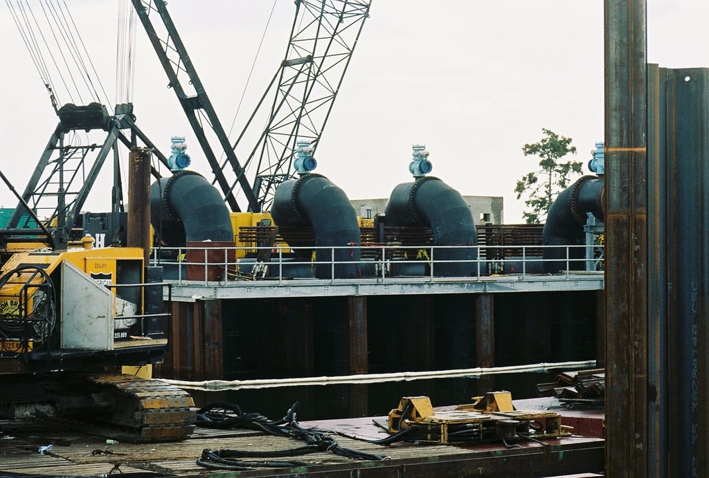
Given a choice - and they are admittedly few - the best place to look for a location for the sensors would be on the straightest piece of pipe possible, as far away from sources of turbulence like the pump discharges or the tees where the 5 foot individual pump lines drop into the 9 foot pipes. The best place, given those parameters, would be on the 9 foot pipes on the lake side of the gates. According to the manufacturer's literature, the "W" type sensors can be placed on a 9 foot pipe and still work just as well. One would not have accurate flowmeter readings from individual pumps, but the existing flowmeters could still be used strictly for indication of flow ("It's flowing, but we don't know if the rate on the display is actually true."). However, one would have a better feel for the overall flow for the set of two or three pumps going into each of those nine foot pipes. Here's a picture of the lakeside location at 17th Street, taken from NPR's May 18th article about what's going on with the pumps:

Here's an overhead shot of 17th Street taken from a May 4, 2007 WWL-TV report, which shows the substantial length of straight pipe available:

The choice at Orleans isn't so great, since the straight section of the 9 foot pipes aren't nearly as long as at 17th Street (picture also taken from the May 18, 2007 NPR article):

As you can see, there are no sensors currently strapped to these locations.
London is about the same as Orleans, since it was designed by the same firm - URS (screen capture from April 30, 2007 WWL-TV report, sorry about the quality):

A closer view of the 9 foot pipes can be found in this USACE photo, previously shown in my October 21, 2006 post:
The second problem is more logistical in nature, but no less severe. One might think that the measurement of the flow is merely an academic matter. It's nice to know, but don't we just want to turn the pumps to "11" and let 'em rip? Well normally, yes. But remember that there's not enough pumps at the lakefront to match the what can be put into the canals on 17th Street and London Avenue. In addition, the Safe Water Levels must not be exceeded (By the way, that's going to be real tricky on London Avenue, considering that the pumps were specified to run at around 4 feet above mean lake level, which is also the safe water level on the canal. Modifications to the discharges of the 9 foot pipes have supposedly allowed the pumps to run at a lower height - perhaps 2 or 3 feet, but who knows if that's actually true?).
When one takes both these circumstances - too few floodgate pumps and the Safe Water Levels - into account, it becomes clear that there is a delicate balancing act to be peformed between the New Orleans S&WB pump operators in stations 6 (17th St), 7 (Orleans), 3 and 4 (London Avenue) and the Corps pump operators at each of the gate structures. The way that that balancing act is performed is by relying - in part - upon the readings from the flowmeters, which are piped through the SCADA system to the computer terminals in each pump station (except pump station 4 on London - I assume messages to the operators in that station will be relayed via the folks in station 3).
The Floodgates Operating Manual recognizes this. Here's the section titled "Step 9 (T - 6 hours)" (sorry, but the Corps isn't big on paragraph breaks. This is exactly as it appears in the manual):
"Conditions will rapidly deteriorate in the final six hours before landfall. Activities at the structure should be completed and all team members should be in safe and secure positions. The H&H Team will continue to monitor the storm and the predictions. The Canal Captains will need to closely monitor the canal levels since rainfall will likely begin to increase, leading to increased pumping at the canal pump stations. Through the working relationships established in the Water Control Plan, the Canal Captains will primarily be observers at the Local Partner pump stations but if the canal level rises to one foot below the Safe Canal Levels they will notify the pump operators and continue to communicate with the operators to verify they are adjusting pumping accordingly. If canal levels rise to the Safe Canal Levels then the Canal Captains will notify the pump operators and continue to communicate with them to ensure they adjust pumping to not exceed the Safe Canal Levels. The Canal Captains will remain in contact with the Operations Chief throughout the storm and inform the Operations Chief when the pump station pumps have either been throttled back or shut down. The procedure will reverse when canal levels lower and the Canal Captains will inform the pump station operators when canal levels are below Safe Canal Levels so they can adjust pumping accordingly. For steady flow conditions, the targeted level for the canals will be in the range from 3 to 4 ft. (NAVD88 Datum) this will provide desired suction head to maximize flow for Interim Control Structure Pumps while not approaching the Safe Canal Levels. Flow meters will provide discharge flow rate data for each Interim Canal Structure Pump. Canal Captains will coordinate with Local Partner Pump Stations to achieve steady flow under these conditions."
A few notes are necessary. First, let me explain the numbers on the "targeted level" in the above paragraph.
The only copy of the manual that has been released is from July of last year. At that time, the Safe Water Level was 5 feet at both 17th Street and London Avenue. Since then, the SWL has changed to 6 feet at 17th Street and 4 feet at London Avenue. Elsewhere in the manual, levels one foot below the safe water level are noted as the activation depths for the floodgate pumps. Thus for London Avenue, the steady flow operating range is probably 2 to 3 feet now, not 3 to 4 feet. And for 17th Street, the range might be 4 to 5 feet, or it might have stayed the same.
Also, the Canal Captains are the Corps Operations representatives in the S&WB pump stations. They'll be huddled over the readouts from the SCADA system, checking the canal depths from the level gauges and the flowmeter readings from the floodgate pumps. As one can see, the flowmeter readings will be part of the data considered by Corps personnel in their decisions to advise S&WB personnel to turn off the city's pumps.
For storms below category 3, Corps personnel are supposed to remain at the floodgates. Supposedly, they'll button themselves up in the little bunkers on the drive platforms, but considering the courage it takes to volunteer for such duty, I seriously doubt they will stay inside if there's a problem or if a request comes over the radio to check a flowmeter out on the pump platforms. Thus, there will likely be a backup for the flow signal received in the S&WB pump stations in the form of Corps Operations person who can look at the local display at the gates, as well as look at the pumps themselves.
Problems arise, however, when the storm is a category 3 or above. In that case, the operators are supposed to evacuate the floodgates. Now, I think it's questionable that they will do so. After all, these guys are probably pretty dedicated, and would most likely have to be escorted off the drive platforms at the point of a gun. I would compare that to the situation exemplified by the S&WB drainage pump operators who stayed during Katrina.
However, sometimes orders are orders, and you must leave. That situation is demonstrated by the evacuation of Jefferson Parish's pump operators during Katrina. With the operators gone, and with no automated system to control or adjust the pumps, the lake backflowed through the JP pump stations into most of the east bank of Jefferson Parish, a totally manmade disaster.
So for truly nasty storms (cat 3 and above), there might be no crews out at the floodgates. In addition (and this is according to the manual) for category 4 or 5 the Corps also pulls the Canal Captains out of the S&WB stations and relocates them to the Corps headquarters on Leake Ave at the river. The S&WB determines whether to leave the S&WB operators in the S&WB stations.
What this means is that all the data to determine whether to turn off more city pumps than will already be turned off (and they will be turned off after the gates drop; otherwise, they'd overwhelm the Corps pumps) will be received via the SCADA system. This includes the data from the flowmeters, which is most likely inaccurate, possibly greatly so.
So two questions need to be asked:
1) Assuming that the use of ultrasonic flowmeters was the correct choice in this application, does the Corps know how accurate the data from those flowmeters actually is? That is, has anyone done detailed baseline tests to determine whether there really is an error due to the current installation position of the pump flowmeters?
2) Does the Corps plan on running drills in which there are no operators interacting with the machinery at the floodgates, in order to determine whether there are kinks which need to be worked out? After all, their plans call for the floodgates to be evacuated in heavy storms.
posted by mcbrid35 at
10:27 AM
![]()
![]()

7 Comments:
This is incredible. And ominous.
By nolareno, at May 22, 2007 8:36 PM
MATT -
You are such a little weenie. I just came back to your blog and you deleted all of my critical comments.
You don't really want to post the peer-reviewed REALITY here do you?
I can't stand the Bush mobsters, but I REALLY despise dishonest engineers like you that post their own opinion, declare it to be absolutely gospel science, and then remove/dimiss all respondent commentary!
YOU are as bad as the BUSH PEOPLE!!
By Anonymous, at May 29, 2007 10:55 AM
Alright, here are a few of my comments on the flowmeters:
* Ultrasonic meters are very persnickety. They need the flow to be just right to give good readings. If you follow the directions, they work great. If not, then you generally get gobldygook. You aren't off by 30% or 40%; you get "ERROR." No reading whatsoever. Not what you want in the middle of a storm.
* Metering this amount of flow is difficult. If I were doing it, I'd run a line in parallel to each flow line and put a turbine meter in. Turbine meters are extremely simple , cheap, and reliable. If you run the meters in slipstream with the main flow, you can get a proportional sample of the flow that can then be scaled upwards to get the total flow. While not ideal, this method is used for fiscal metering in extremely large oil wells, so it's not something to thumb your nose at. Done correctly, it's quite accurate and very robust. I just requires a little out of the box thinking.
By Clay, at May 31, 2007 10:46 PM
Clay, it's comments like yours that I'm proud to post. The slipstream idea is so common-sensical that naturally it wasn't thought of.
And your comment about ultrasonics being less-than-agreeable is right on the money. There's other things that can go wrong in this application (I didn't want to clog up the blog entry, but here's the other stuff I'd thought of):
1) The sensors are mounted on the outside of the pipe, not through the pipe wall, so the accuracy of the reading depends on the goopy substance (called "couplant" - the same stuff you see applied to a pregnant woman's belly during an ultrasound) being in perfect contact between the sensor and what the sensor is mated to (I'm not sure if it's the pipe itself or a little plate that fits to the pipe). If that couplant isn't spread completely, or if it's washed away by rain (conceivable, considering there's no "roof" to divert rain away from the sensors), goodbye flow reading. Ultrasonic signals can hardly travel through air. They need perfect, complete physical contact between solid or semi-solid substances to propagate.
2) The manufacturer recommends these sensors for pipes with an isotropic makeup, such as plastic. The grainy structure of steel (which is what the pipes are at the gates) makes it more likely for the ultrasonic signal to get attenuated before it even hits the water. More signal loss means less accuracy.
3) There's other signal-processing considerations as well. Do we know how far apart the two flow readings (which are averaged to get the final reading) are allowed to be before the meter says "Error?" Ultrasonics are so sensitive, and really aren't meant for such a rough-and-tumble environment. This looks like a move made by someone with hardly any experience in flow metering.
More and more, I worry that this poor decision (either by the Corps' electrical guy Dan Bradley, or by a contract engineer or a suggestion from the controls contractor - Prime Controls) to go with these things is really going to ruin New Orleans. The engineering is just so poor, I can't believe that more engineers like yourself aren't writing in.
By the way, the Floodgates Operating Manual gives another example of cruddy engineering that fortunately never came to pass. However, it gives an indication of a misguided infatuation with ultrasonics.
In the last few pages, there's extensive decription of ultrasonic level detectors to be installed next to the pumps. They would have been the primary means for turning pumps on and off once the floodgates are evacuated in heavy (Cat. 3 and above) storms. They were meant to operate in a very narrow range between 2 and 4 feet above sea level. How in the world someone could think that non-contact level sensors could work accurately for detecting the level of water in a 100 foot wide canal with wind-driven waves, floating debris (e.g. tree branches), and vortices induced by the pumps themselves is beyond me. As a storm is raging around them, the canals will not be calm, level bathtubs.
I've been told these sensors were thankfully never installed. I assume they're using float switches, which are mentioned as the backups in the manual.
By mcbrid35, at June 01, 2007 9:12 AM
I've got to disagree with you on a couple of points:
1- The couplant is a pain to deal with. It's quite messy. But, it tends to stick pretty well. The rain hasn't been that big an issue with the meters I've dealt with.
2- Plastic piping is more forgiving when it comes to mounting, but as long as the meter is set up correctly, there's nothing wrong with mounting them to carbon steel piping.
3- Ultrasonic can be used in much harsher environments, like deepwater offshore platforms. You've just got to do it right.
I've got one straightforward question for you: How many true Instrumentation Engineers does the Corps have? I know that they overwhelming majority of Corps engineers are Civil or Environmental. They have very few MechE's. Even fewer EE's.
You hit the nail on the head with the engineering judgment comment. That's what disturbs me the most. I can deal with sloppiness in selecting vendors/equipment. Piss poor engineering judgment is what scares the hell out of me.
Also, FYI- I'm not "technically" an engineer under Louisiana law. I'm an E.I. with a little over a year's experience. I won't be eligible to take the P.E. for another 3 years or so. IIRC, under Louisiana law, only P.E.'s can call themselves engineers.
That fact should scare people even more. I'm only a couple steps above a rank amateur and if I can call the Corps on major mistakes, you've got to wonder what the really senior engineers in the area think about some of these designs.
By Clay, at June 01, 2007 11:46 AM
Here are the most common ultrasonic screwups, in my experience:
* Improper mounting (probe separation, upstream and downstream pipe diameters, tight contact, etc.)
* Flow conditions (swirl is a big danger)
* GVF/multiphase flow (gas or air in the liquid stream wreak havoc on the measurement, even in fairly small amounts [say, 10% Gas Void Fraction]).
* Wrong transducer
* Wrong signal frequency
* Wrong input parameters (CS pipe, wrong liquid/gas, etc.)
By Clay, at June 01, 2007 11:52 AM
I'm pretty sure the Corps relies heavily on contract engineers for I&E. See my previous comment above for the likely suspects involved in these decisions.
And while it's easy to get bogged down in the details of this particular box the Corps has placed themselves inside, I think it's important to step back and realize that this stuff is meant to guard lives. It should be the best, most robust technology available.
I have yet to see any evidence that engineering design decisions since Katrina aren't severely driven by budgetary and schedule considerations, not what should be the guiding principles of public safety, honor and integrity. You can see that in all of previous engineer-y posts about flaws in the pumps and the gates.
These floodgates are not some routine repair of a levee that's guarding farmland in the middle of nowhere. They are the capstone project in one of the highest-profile engineering efforts in the world, after a lethal engineering failure that killed over 1500 people. They are incredibly important to everyone, including the Corps; General Van Antwerp stood in front of the 17th Street gates for his 5/31/07 press conference.
However, despite all this obviousness, it looks like everything has been done on the cheap without a lot of thought. South Louisiana is filled with tons of experienced engineers who know everything about everything when it comes to pumping. It just doesn't look like any of that talent was tapped. Heck, the GAO reported that the New Orleans District didn't even have a specification for the pumps, so they copied MWI's. How can an office tasked with flood protection and drainage for decades not have a specification sitting on the shelf for drainage pumps? Did they start the Pritchard Place pumping station project in Hollygrove (which uses MWI electric pumps) without specs as well?
It all points to really cruddy engineering across the board.
By mcbrid35, at June 01, 2007 12:10 PM
Post a Comment
<< Home