Fix the pumps

Tuesday, October 20, 2009

Silted In

What do we know about Options 1 and 2?

- The Corps has been playing with information on the projects, redacting critical figures that show serious discrepancies in their cost estimates. Then, they've been attempting to scare the public into Option 1.

- The Corps claims they are only authorized to proceed with Option 1. However, we know it was the Corps that made a CHOICE to proceed with Option 1 over Option 2 just months after Katrina with no public consultation. They drafted legislation for Congress - eventually adopted unchanged from the original language - which locked Option 1 in. That "lock in" is according to the Corps' lawyers' interpretation of that Corps-drafted legislation. And the circle of legalism is complete.

- The Corps cost estimates for the Option 2 stations are likely wildly inflated. Between 2006 and 2009, the estimate ballooned over $1 billion. That is even taking into account a very generous 60% contingency on the 2006 estimate.

- The Corps' plans for Option 1, which they claim will allow adaptation to Option 2 later, are actually not as adaptable as all that. Their Option 1 stations leave out key features which will be necessary for Option 2, such as formed suction intakes (FSI's) on the pumps, as well as gearboxes, electric motors and support equipment which is sized for both Options 1 and 2.

- The Corps' plans for Option 1 also leave the outfall canal walls untouched, even though their own reports say those I-walls should be replaced with T-walls if the Corps proceeds with the plans they are currently proposing. The reports show that future pump station operating costs will eventually outstrip the cost to fix the walls now. Even so, the Corps is showing no inclination to do the right thing and fix the walls.

With all that in mind, it is valuable to examine what New Orleans and Jefferson Parish will be left with if Option 1 proceeds as the Corps wishes.

First up, the canals...

Put simply, the current canals are a mess. They appear to be filling with silt, impeding the drainage capacity of the city. The silt also raises the water level on those weak walls, making every major rainfall event riskier. As more and more water is pumped out of the city, more silt is deposited in the canals. Eventually, there will be so much silt, the canals will not be able to convey enough water without exceeding safe water elevation restrictions.

Silting as of 2006

The problem of silting is well known. It appears in diagrams in the 2009 B&V report. Those diagrams are based on other diagrams from another Black & Veatch report, this one from 2008. That 2008 report analyzed various flow scenarios, attempting to quantify how often the gates need to drop at the lakefront based on rainfall, lake level, and existing & future safe water levels.

The diagrams include hydrographic survey results from the post-K years (likely 2006), showing the "current" canal bottoms. Here they are for two of the canals (my annotations are in red):

17th Street:

London Avenue:
As you can see, in 2006 there were significant stretches of those canals with a lot of silt in them. There's no reason to think anything has changed (see "Where did the silt come from?" below).

I have a few caveats to these diagrams:

a) I'm having problems finding the bottom elevations of the Orleans Avenue canal from the early 90's. If I can get them, I'll make a diagram like the ones above and add it to this post later.

b) I pulled the old canal bottom and wall top elevations from the as-built drawings of the work done on both these canals, available at the IPET site (17th Street here, London Avenue here and here). The datum on those drawings was NGVD29. Now it is NAVD88. According to this document from the London Avenue load test, the conversion is NAVD88 = NGVD29 - 1.5 feet. I'm not sure if that is true or not, and I'm not particularly qualified to say so. However, for the point I'm trying to make - there's a LOT of silt in the canals - I don't believe it matters.

c) Notice the sections in the canals closer to the lake on the London Avenue canal that apparently have gotten much deeper than the -10 feet NGVD (or -11.5 NAVD) original depth. The section at the Robert E Lee Blvd bridge shows a great deal of scour. It is right in front of the "London North" breach. Since the London Avenue survey was done in March, 2006, it would make sense there would be a large scour hole right in front of the breach area at that point, before the area had been completely repaired. It's unclear if filling this hole was part of the Corps work done in that vicinity after Katrina - the hole may still be there.

One last thing on the data from 2006... The Corps had the London Avenue survey from March of 2006 turned into a video:


This video, which travels from south to north along the canal, backs up the graphic above. The areas in pink and orange are those that have lots of silt (water depths from -4 to -7 feet), and they are concentrated in the area to the south of Mirabeau Avenue. The large scour hole at Robert E Lee also shows up in deep purple (water depth of -20 feet). Most of the canal north of Mirabeau - shown in green - appears (as of March 2006) to be at nominal depth, which is in the range of -9 to -12 ft. It's somewhat interesting that there are some areas of scouring around the bridge foundations, shown in light blue (-13 to -14 feet).

Where did the silt come from?

There's two possibilities here:

1) There's always been a silting problem on the canals.
2) Katrina

While we know (1) to be true (it was why dredging was done on the 17th Street canal in the late 80's and early '90's leading to the breach), the possibility that much of this silt is from Katrina is quite strong.

Thousands of tons of silt from Lake Pontchartrain flowed into the city through the breaches in the outfall canals after Katrina. The city's Public Works department has spent years trying to get it out of the subsurface drainage system. Other canals all over the area were similarly clogged and had to be cleaned out.

What is interesting is that while the Federal government has picked up the tab to for all those cleanouts, there was no move to do the same for the three biggest areas of potetial cloggage: the outfall canals. Thus, it is possible the New Orleans area is now living with a huge legacy of Katrina - stopped up drains. The right thing to do would have been to do some dredging in combination with replacement of the weak sections of the walls soon after the storm, but the Corps foreclosed that possibility by eliminating Option 2 (or any remedial work on the walls) from consideration in late 2005 and early 2006 - with no public consultation.

Now the area is stuck with a problem that is very difficult to solve. Nonetheless, dozens of other culverts and canals have been cleaned out of Katrina debris at Federal expense since the storm; the right thing to do would be to address this problem - safely if possible.

Is it getting worse?

So is the problem getting worse? According to data collected earlier this year by the Corps, it appears at least one canal may be silting up somewhat quickly.

In May, 2007, the Corps issued a study to determine the safe water level for the 17th Street canal. The complete version (just released this year as part of the IER #5 comment process and which includes graphics in the back) is here. It concluded that 6 feet was okay, if some work was done in certain spots near the I-10 and Veterans Blvd. bridges. That work was completed shortly afterward, and the safe water elevation has been 6 feet ever since.

Of course, that study was completed before new hurricane protection design guidelines were promulgated in October, 2007. Two years later, the Corps is still studying safe water elevations on the canals, using those new guidelines. Results are not expected until the beginning of the 2010 hurricane season, or almost five years after Katrina and two years after permanent protection was originally promised to be complete.

Part of the 2007 17th Street canal study was a section on silt build up in the canal:

"(3) Sedimentation. The post Katrina surveys show that the accretion has occurred in the canal. Between I-10 and the railroad bridge the lowest canal bottom elevation is El. -10 NAVD or over 7 ft. of sedimentation according to post Katrina surveys. Between Veterans Blvd and I-10 the canal bottom elevation is El. -14 to -18 NAVD or between .5 to 3 feet of sedimentation according to post Katrina surveys. Between the B/L Station 583+00 and Veterans Blvd the canal bottom elevation is El. -15 NAVD or higher about 4 feet of sedimentation according to post Katrina surveys. Between Hammond Highway Bridge and Station 583+00 the canal bottom is between El. -17.5 NAVD and El. -19.5 NAVD (at one location 120 ft south of Hammond the bottom elevation is -20.0 NAVD)about .5 ft to 2.5 ft of sedimentation. Since the surveys were taken 18-inches of riprap has been placed on the canal bottom from Hammond Highway to the south end of the breach."

As part of the ongoing, neverending process of evaluating the safe water levels that I mentioned above, the Corps had a new survey done of the 17th Street canal this spring. The report for that survey is here, and the raw data is here.

After reading through that data, the above paragraph could be rewritten to read:
"(3) Sedimentation. The post Katrina surveys show that the accretion has occurred in the canal. Between I-10 and the railroad bridge the lowest canal bottom elevation is El. -10 NAVD or over 7 ft. El. -7 NAVD or over 10 ft. of sedimentation according to post Katrina surveys. Between Veterans Blvd and I-10 the canal bottom elevation is El. -14 to -18 NAVD or between .5 to 3 feet El. -10 to -15 NAVD or between 2 to 7 feet of sedimentation according to post Katrina surveys. Between the B/L Station 583+00 and Veterans Blvd the canal bottom elevation is El. -15 NAVD or higher about 4 feet El. -13 NAVD or higher about 6 feet of sedimentation according to post Katrina surveys. Between Hammond Highway Bridge and Station 583+00 the canal bottom is between El. -17.5 NAVD and El. -19.5 NAVD (at one location 120 ft south of Hammond the bottom elevation is -20.0 NAVD)about .5 ft to 2.5 ft of sedimentation between El. -14 NAVD and El. -18 NAVD about .5 ft to 4.5 ft. Since the surveys were taken 18-inches of riprap has been placed on the canal bottom from Hammond Highway to the south end of the breach."

So that is saying that in the space of about three years, some sections of the 17th Street canal have had 3 to 4 feet of silt build up in the canal. Considering that those particular sections have a design depth of approxmately -18.5 feet (see notes below about the canal bottom elevations), and have gone from 7 feet to 10 feet of sediment, the canal is clearly getting clogged up to the point where drainage capacity will soon be impeded.

What is the upshot of all this?

It means that the problem which led in part to the failure of the 17th Street walls during Katrina - the need to dredge the canals due to the buildup of silt - will not go away with Option 1, the Corps' preferred alternative. It also means that at the rate the silt is apparently building up in the canals, the need to dredge may come sooner rather than later. That should be worrying, considering what happened the last time the 17th Street canal was dredged.

In addition, the Corps might put forward a rather bizarre argument - silting of the canals is good. In Appendix B to the London Avenue Load Test report, the Corps paid consultants studied how the permeability of silt on the canal bottoms can prevent the walls from getting undermined like in Katrina. They concluded,
"Analyses have shown that when there is direct hydraulic communication between the canal water and the sand layer, high toe exit gradients and large uplift pressures can exist, even for modest canal water levels. If the canal was 'silted in,' then these exit gradients and uplift pressures are substantially reduced."

In non-engineerese, that means the silt is blocking water from getting under the walls.

These are the kinds of crazy situations and arguments that these faulty walls create - is it more valuable to silt in the canal, reducing drainage capacity, just so you can save some crummy walls? Or should the canals be dredged, possibly opening up seepage paths under the walls, and maybe even damaging them in the process? It's ridonkulous.

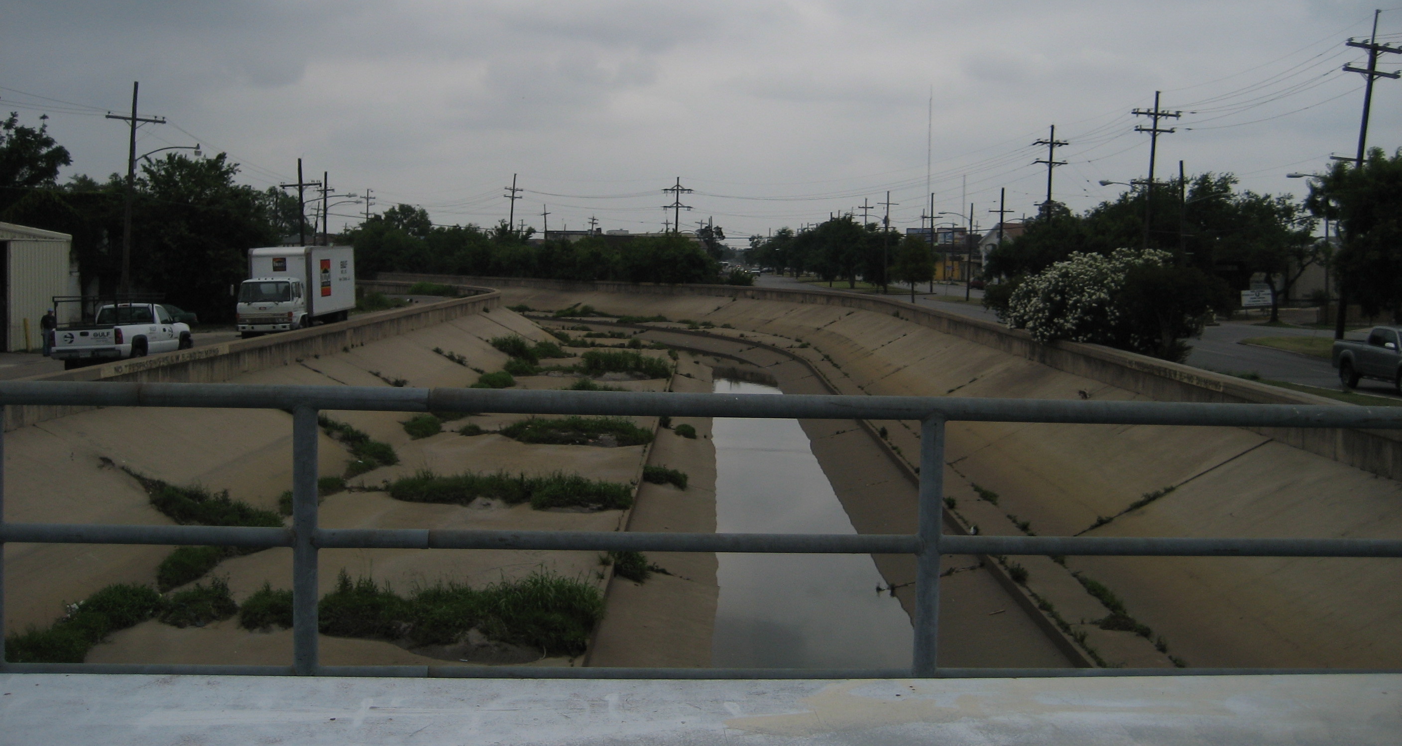
What would solve this? In the short term, some federally funded cleanups would seem to be in order. However, in the long term, concrete lined canals with a nice gentle slope that would keep the silt moving during drainage operations are the best choice. Such canals already exist all over the metro area. The Palmetto Canal - which leads to the 17th Street canal - as been concrete lined for a very long time and does not appear to have a silting problem along its length. It also doesn't have any walls, since it is subsurface. Here's a picture:


(image courtesy user "Infrogmation" at wikimedia.org)

Now, even with a concrete channel, the silt doesn't magically disappear. It builds up wherever there is an obstruction in the canal. This would include bridge foundations and the inlets of the lakefront pump stations. However, installing lowered concrete canals would significantly reduce the current problem to just those spots, and would also keep future dredging operations from the weakened walls and levees - since those walls and levees would not exist.

This is just one of the unannounced problems that will remain for the New Orleans area if Option 1 is allowed to proceed. There are others...

Thursday, October 15, 2009

Pennywise Part 4

Previously: Part 1 Part 2 Part 3

[Pardon the copying of verbiage from Parts 1, 2 and 3 at the beginning of this part. You can scroll down past the main list of 13 features to see the new content]

The largest refrain from those in support of Option 2, which is everyone but the Corps, is that effective flood protection is better than cheap flood protection. Supporters of Option 2 say it is just plain better than Option 1, a position even the Corps agrees with in a technical evaluation report mandated by Congress. The problem New Orleans and the surrounding area faces is that the Corps is cheaping out and going for Option 1 over Option 2, which is exactly what the Corps chose to do just months after Katrina, even though they believed it would only take another $190 million to do Option 2. Admittedly, it may have cost a little more to do Option 2, but based on the facts at the time - and what was passed up the chain to the White House and Congress - the Corps CHOSE to do Option 1 to save $190 million, and drafted the authorization and appropriation language to match it. The cheaping out began a long time ago.

However, I would go further and say that the Corps is cheaping out even on how they are planning to build Option 1. I believe they are deliberately lowballing the Option 1 estimate in order to make it look like the only way to go. They are doing this through a combination of shifting some features to future Option 2 and simply not building other features. If they didn't, it would be revealed that even Option 1 - if it was truly to be built correctly and be adaptable to Option 2 - cannot be built for the $804 million the Corps told Congress to give it.

In part 1 of this series, I introduced the various flavors and features of the Option 1 pump stations as they are laid out in three primary sources:

a) The 2009 Black and Veatch report
b) The 2009 Congressional Cost Report
c) A presentation given by the Corps to the SLFPA-E (east bank levee authority) on October 1, 2009.

See that earlier post for an explanation of the three flavors of Option 1 from the 2009 B&V report.

For reference, here's the description from the Cost Report:
"Pumping Plant - The pumping stations include the pumping station building and equipment, intake wet well, discharge section, canal transitions, generators with enclosures, a tank farm, and all the ancillary systems required for a fully functional facility. A cofferdam is required for the contruction of the pumping station. A temporary bypass may also be required to route canal flows around the cofferdam during construction."

And here are the renderings from the October 1, 2009 presentation. First, the plan for Option 1:


and the plan for Option 2:

The list of pump station features from the 2009 B&V report is:

1) Includes Floodwall/Levee Upgrades
2) Includes Gated Bypass
3) Canal Transitions
4) Deepened Sill
5) Formed Suction Intake
6) All Electric Pumps
7) Pump Station Sized for Future Pump Capacity
8) Pump Capacity Sized for Future Pump Capacity
9) Fuel Storage and Generator Sized for Future Capacity
10) Includes Siphon Recovery
11) Includes Breakwater
12) Stilling Basin at Discharge
13) Removal of ICS Facilities

As I've noted above, we've already covered the first nine features. In this post we'll move on to the last 4...

10) Includes siphon recovery

Siphon recovery is an arrangement of the discharges of the pumps that allows recovery of energy of the water as it exits to the lake. It is a big hump in the discharge tube that, once water is flowing through it, sets up a siphon that knocks the required head of the pumps down to the difference between the canal and lake levels (along with losses through the station). It also acts as a backflow prevention mechanism by virtue of the bottom of the siphon peak being above the lake surge level. Note, however, this is not as reliable a backflow preventer as a flapper gate or some other positive closing mechanism.

Here's a detail from the October 1, 2009 SLFPA-E presentation showing the siphon recovery section:


All of the options include siphon recovery, so there's really no discussion about other options here.

On a related note, though, it is imperative these stations include two forms of backflow prevention, per governing Corps standards. For many more details on this see my 2006 posts on backflow prevention, "Flappers vs. siphons" and "Follow up on flappers vs. siphons."

11) Includes Breakwater and 12) Stilling Basin at Discharge

These two options together represent a choice for prevention of waves entering the discharge tubes of the pumps.

The Corps has chosen breakwaters at the 17th Street and Orleans Avenue sites. At London Avenue, they are siting the station back from the lake at a position they claim will attenuate any waves before the pump discharges are impacted (based on a 1987 Corps study).

Waves could wreak havoc on the pumps. If the water level at the discharge (i.e. lake) side is constantly changing, the pump will have to work harder over very short periods of time. The 2009 B&V report describes the situation thusly:
"If the lake has a wave of 9 feet striking the face of the pump station, then the pumping unit will be exposed to the pulsations equivalent to the 9 feet. For a pumping unit rated at 12 feet, this is a significant increase possibly doubling the operating head acting on the pumping unit which could result in permanent damage to the pumping units or decrease the pump service life. Several pump manufacturers were contacted regarding this issue. Generally, pump manufacturers indicate that additional testing must be performed to determine the impact that waves will have on the pumping unit."

The breakwater is a manmade speedbump for waves on the lake side of the stations. it has to be big enough to knock down most of the energy of the waves so that only minimal (1-2 feet) waves reach the stations. The 2009 B&V report includes a drawing of the cross-section of the breakwater:


The other method of keeping waves away from the pumps is putting up a big wall right in front of the pump siphon discharges, creating a huge box where water would come to rest before flowing gently into the lake over the top of the wall. The wall would serve the same function as a breakwater, but it would be a lot closer to the stations. This "stilling basin" would necessarily have a higher water elevation in it since the front wall would need to be tall enough to knock down waves which were on top of a surge. There's a drawing of a stilling basin in the 2009 B&V report:


This higher discharge water level would reduce the advantage of the siphon and would make the pumps work harder, meaning larger motors, gearboxes, generators, buildings, and the like. It's not exactly the best choice, which is probably why the Corps went with the breakwaters. However, it's truly impossible to know whether it was the best way to go from an economic point of view, since the Corps has redacted all that information out of the 2009 B&V report.

One final note on this. The IER #5 has 159 instances of the word "breakwater," but none of the word "stilling." Had the 2009 B&V report been released during the IER #5 comment period in May, people may have considered whether a stilling basin was a superior alternative to the two breakwaters proposed for 17th Street and Orleans Avenue. But the public was never availed of that opportunity, since the existence of the B&V report was never confirmed until well after the end of the comment period.

13) Removal of ICS facilities

Part and parcel of this whole project is that these new stations replace the current Interim Closure Structures (ICS). Every plan calls for that, though the Corps has looked at what it would take to keep the current ICS facilities in place. It would be far cheaper to do so than to build new stations.

I'm going to hold off on talking about this particular topic because it deserves a post of its own. For the sake of this post, suffice to say that every plan calls for getting rid of the ICS facilities after the mew pumping stations are brought on line.

Summary

So that's all the various features that make up the pump stations, as listed in the 2009 B&V report. From what I've read, it would appear the Corps has cheaped out on the following features for their Option 1 stations:

1) Includes Floodwall/Levee Upgrades - no upgrades appear to be planned, even though the inclusion of gates would seem to require it on two of the three canals.

3) Channel transitions - the Corps wants to put a turbulence-inducing retaining wall, or "step," to account for the elevation difference between the current canal bottoms and the lowered sills. In the long run this will cause damage to the pumps and will be a maintenance headache with silt building up at the bottom of the step.

5) Formed Suction Intakes - the Corps knows these will be required for Option 2, just like the deepened foundation they are already including. However, they are not including them in their version of Option 1, pushing the FSI costs into an Option 2 at an indeterminate future time. This appears to be a direct instance of the lowballing of Option 1 costs and the inflation of Option 2 costs.

6) All Electric Pumps - This "feature" only truly appears in the Cost Report. There will undoubtedly be diesel pumps in the pump stations, so this is probably another effort to drive down the reported cost of Option 1 at the expense of reality.

7) Pump Station Sized for Future Pump Capacity
8) Pump Capacity Sized for Future Pump Capacity
9) Fuel Storage and Generator Sized for Future Capacity

These three features leave out the actual equipment that would accommodate future interior drainage expansion by the Sewerage & Water Board, including only space for the equipment. This is another way to minimize reported cost.

Also, the Corps is only planning on installing pumps, motors, gearboxes, switchgears, and other pump-related equipment that is sized for Option 1, rather than looking ahead and installing oversized equipment which could be recycled for Option 2. Again, this chops current costs while raising the bills in the future, making Option 1 look better at the expense of Option 2.

As you can see, the Corps has done as much as possible to drive down the reported costs for Option 1. In some cases they have eliminated features like FSIs and diesel pumps from their Option 1 cost estimate in order to squeeze that square peg into their $804 million round hole. In additon, they appear to have passed some of those costs on to Option 2, making that Option look that much less attractive. When combined with the increase of $1 billion in the Option 2 station costs in the span of 3 years, it's obvious there's little to trust in the Corps' estimates, which makes the decisions being made based on those estimates suspect as well. And of course, their entire plan leaves the same, defective floodwalls in place along the canals for New Orleans to deal with.

The best way to proceed, rather than allowing the Corps to play with the numbers and the designs, is to get an independent estimate of the permanent pumps project while all the features that are common to Options 1 and 2 proceed. Simultaneously, the Corps should shift money to the permanent pump project to accommodate all those common features.

Unfortunately the move for an independent study slowed when the Landrieu/Vitter amendment to the 2009 Energy & Water Resources appropriations bill - which authorized such a study - died in conference in September. It still needs to happen, because the Corps simply cannot be trusted with this project at this point.

Previously: Part 1 Part 2 Part 3

Pennywise Part 3

Previously: Part 1 Part 2

[Pardon the copying of verbiage from Part 1 and Part 2 at the beginning of this part. You can scroll down past the main list of 13 features to see the new content]

The largest refrain from those in support of Option 2, which is everyone but the Corps, is that effective flood protection is better than cheap flood protection. Supporters of Option 2 say it is just plain better than Option 1, a position even the Corps agrees with in a technical evaluation report mandated by Congress. The problem New Orleans and the surrounding area faces is that the Corps is cheaping out and going for Option 1 over Option 2, which is exactly what the Corps chose to do just months after Katrina, even though they believed it would only take another $190 million to do Option 2. Admittedly, it may have cost a little more to do Option 2, but based on the facts at the time - and what was passed up the chain to the White House and Congress - the Corps CHOSE to do Option 1 to save $190 million, and drafted the authorization and appropriation language to match it. The cheaping out began a long time ago.

However, I would go further and say that the Corps is cheaping out even on how they are planning to build Option 1. I believe they are deliberately lowballing the Option 1 estimate in order to make it look like the only way to go. They are doing this through a combination of shifting some features to future Option 2 and simply not building other features. If they didn't, it would be revealed that even Option 1 - if it was truly to be built correctly and be adaptable to Option 2 - cannot be built for the $804 million the Corps told Congress to give it.

In part 1 of this series, I introduced the various flavors and features of the Option 1 pump stations as they are laid out in three primary sources:

a) The 2009 Black and Veatch report
b) The 2009 Congressional Cost Report
c) A presentation given by the Corps to the SLFPA-E (east bank levee authority) on October 1, 2009.

See that earlier post for an explanation of the three flavors of Option 1 from the 2009 B&V report.

For reference, here's the description from the Cost Report:
"Pumping Plant - The pumping stations include the pumping station building and equipment, intake wet well, discharge section, canal transitions, generators with enclosures, a tank farm, and all the ancillary systems required for a fully functional facility. A cofferdam is required for the contruction of the pumping station. A temporary bypass may also be required to route canal flows around the cofferdam during construction."
And here are the renderings from the October 1, 2009 presentation. First, the plan for Option 1:


and the plan for Option 2:


The list of pump station features from the 2009 B&V report is:

1) Includes Floodwall/Levee Upgrades
2) Includes Gated Bypass
3) Canal Transitions
4) Deepened Sill
5) Formed Suction Intake
6) All Electric Pumps
7) Pump Station Sized for Future Pump Capacity
8) Pump Capacity Sized for Future Pump Capacity
9) Fuel Storage and Generator Sized for Future Capacity
10) Includes Siphon Recovery
11) Includes Breakwater
12) Stilling Basin at Discharge
13) Removal of ICS Facilities

As I've noted above, we've already covered the first five features. In this post we'll move on to the next 4...

6) All Electric Pumps

This is an odd one. Including all electric pumps (that is, no diesel-powered pumps) makes the pump costs cheaper, but increases the costs of generators, fuel storage, electrical equipment, and associated structural & civil costs around the generator building.

Also, I can't find any evidence the Corps is actually considering putting in all electric pumps. The IER#5, in both its noise and pollution impact sections, indicates some diesel engines for Option 1. None of the pump mixes in any of the Option 1 OR Option 2 scenarios in either the 2009 B&V report (found in Appendix E) or the 2006 GEC/B&V report include an "all electric pumps" scenario. The only place it pops up is in this small mention early on in the 2009 B&V report (and then never again) and - more importantly - in the Congressional Cost Report.

In the Cost Report, it is made quite clear the cost estimates are based only on electric pumps. In fact, that is the first "key engineering criteria:"
"1. Pumping stations could be equipped with a mix of diesel driven pumps and electric motor driven pumps. For the purpose of this report, electric motor driven pumps were used."
No further explanation is given, but here's my guess: the savings from not installing diesel engines is greater than the increased cost of extra generator equipment for all electric pumps. Thus, the costs would look lower. While overall costs would be lower for both Options 1 and 2, it would only matter in the calculations for Option 1, where the Corps wanted to make it look as cheap as possible. The problem is that it doesn't reflect reality: there WILL be diesel engines inside the stations. The Corps simply said to Congress, "Let's just ignore reality for this report, since it'll make Option 1 cheaper."

7) Pump Station Sized for Future Pump Capacity
8) Pump Capacity Sized for Future Pump Capacity
9) Fuel Storage and Generator Sized for Future Capacity


The "future capacity" referred to here is that capacity the Sewerage and Water Board would like to bring online over the next few years. Through the construction of various new pump stations and drainage culverts, the Board anticipates the following increases in carrying capacity for each canal:

17th Street: increase from 10,500 cubic feet per second (cfs) to 12,500 cfs
Orleans Avenue: increase from 2690 cfs to 3390 cfs
London Avenue: increase from 7980 cfs to 8980 cfs

These three pump station features are designed to take into account the future S&WB expansions. However "take into account" can have multiple meanings.

In the 2006 report, it meant that the Option 1 and the Option 2 pump stations had pump capacities which matched the future S&WB numbers. That is, the 17th Street lakefront stations in both Option 1 and Option 2 had 12,500 cfs of actual pumps. And the buildings and generation capacities matched those larger numbers. The same went for Orleans and London.

Now, three years later, it means a totally different thing.

Now it means that space will be provided for pumps needed in case of future S&WB expansion (i.e. 2000 cfs of pumps at 17th, 700 cfs of pumps at Orleans, and 1000 cfs at London), but the actual pumps and everything that goes with them will not. Only the space for extra generating capacity will be provided. That's what the Corps means when they say such things are "expandable," as if that's an actual feature.

Don't get me wrong - it's nice the Corps is acknowledging the reality of expansion that has been in the S&WB capital budgets for years by building structures that can handle the extra equipment necessitated by that expansion. But three years ago they were budgeting for the actual equipment. Now they're not. Why? Cost.

There's another wrinkle. Since the Option 2 pumps will need bigger motors (for the electric pumps) or engines (for the diesel pumps), it would be possible to purchase bigger motors now for the electric pumps and possibly run them at a slower speed or lower load while Option 1 is in place. Note that it's probably not possible to buy bigger engines now for the diesels, since they can't really be run as light as Option 1 would require without damage. The 2009 B&V report speaks to this:
"Large electric motors are more tolerant of the light loading. Thus oversized electric motors could be installed and operated at a reduced load. The efficiency of the electric motor decreases when lightly loaded and as the motor size increases, the motor starting current required will increase. These factors will increase the required onsite electric generator capacity, but the impact on the number of generators is considered minor. If oversized electric motors are provided on the pumps, the engine generators that provide power to the motors will need to be replaced or additional engine generators would need to be installed when the pump station is converted from an Option 1 to an Option 2 pump station."

In addition, it would be possible to include other pump components in an Option 1 station that could be used in Option 2. Again, from the 2009 B&V report:
"Other aspects of the pumps that could be made similar for the Option 1 and Option 2 pumps at an additional cost are the size of pump shaft and bearings and the gear box. Both the pump shaft and bearings can be oversized to function for both Option 1 and Option 2 pumps. In a similar manner, the gear box could be reused for both options provided that the pump speed is the same. If the pump speed varies between Option 1 and Option 2, the gear drive will need to be modified or replaced to accommodate the change in pump speed."

It does not appear the Corps wishes to include many pump components in the Option 1 stations which could be reused in the Option 2 stations. The slideshow from the October 1, 2009 presentation to the SLFPA-E says as much. Page 16 shows what would be done to the Corps' Option 1 stations to convert them to Option 2:


Further confirmation is provided in the red text boxes on the Option 1 rendering:


"GEAR REDUCER SPECIFIC FOR CURRENT WATER SURFACE ELEVATION"
"PUMP MOTOR SPECIFIC FOR CURRENT WATER SURFACE ELEVATION"
"PUMP BELL AND IMPELLER SPECIFIC FOR CURRENT WATER SURFACE ELEVATION"

"Current water surface elevation" referes to the canals as they exist today, which is what will remain after Option 1 is done.

Only the pump housing and the length of the shaft match Option 2 requirements:

"PUMP COLUMN AND SHAFT DESIGNED FOR BOTH WATER SURFACE ELEVATIONS"

As you can see, much of what they are planning to install on Option 1 will have to be replaced in Option 2, including gearboxes, motors, impellers (that's actually to be expected) and electrical switchgear. With clever planning, much of that equipment could be purchased in Option 1 with an eye toward Option 2, saving money down the line.

However, the rule of the day with the Corps' version of Option 1 is to save money now, and don't worry about future costs. It's quite shortsighted and makes bringing Option 2 to fruition much harder, since it will be unnecessarily expensive down the line.

Next: Part 4
Previously: Part 1 Part 2

Pennywise Part 2

[Updated section on channel transitions - 11-10-09]

Previously: Part 1

[Sorry for the repeat of the two introductory paragraphs from Part 1, but I never know exactly how people are coming to the blog, and if they hit this post frst, they might miss this content]

The largest refrain from those in support of Option 2, which is everyone but the Corps, is that effective flood protection is better than cheap flood protection. Supporters of Option 2 say it is just plain better than Option 1, a position even the Corps agrees with in a technical evaluation report mandated by Congress. The problem New Orleans and the surrounding area faces is that the Corps is cheaping out and going for Option 1 over Option 2, which is exactly what the Corps chose to do just months after Katrina, even though they believed it would only take another $190 million to do Option 2. Admittedly, it may have cost a little more to do Option 2, but based on the facts at the time - and what was passed up the chain to the White House and Congress - the Corps CHOSE to do Option 1 to save $190 million, and drafted the authorization and appropriation language to match it. The cheaping out began a long time ago.

However, I would go further and say that the Corps is cheaping out even on how they are planning to build Option 1. I believe they are deliberately lowballing the Option 1 estimate in order to make it look like the only way to go. They are doing this through a combination of shifting some features to future Option 2 and simply not building other features. If they didn't, it would be revealed that even Option 1 - if it was truly to be built correctly and be adaptable to Option 2 - cannot be built for the $804 million the Corps told Congress to give it.

In part 1 of this series, I introduced the various flavors and features of the Option 1 pump stations as they are laid out in three primary sources:

a) The 2009 Black and Veatch report
b) The 2009 Congressional Cost Report
c) A presentation given by the Corps to the SLFPA-E (east bank levee authority) on October 1, 2009.

See that earlier post for an explanation of the three flavors of Option 1 from the 2009 B&V report.

For reference, here's the description from the Cost Report:
"Pumping Plant - The pumping stations include the pumping station building and equipment, intake wet well, discharge section, canal transitions, generators with enclosures, a tank farm, and all the ancillary systems required for a fully functional facility. A cofferdam is required for the contruction of the pumping station. A temporary bypass may also be required to route canal flows around the cofferdam during construction."

And here are the renderings from the October 1, 2009 presentation. First, the plan for Option 1:


and the plan for Option 2:


The list of pump station features from the 2009 B&V report is:

1) Includes Floodwall/Levee Upgrades
2) Includes Gated Bypass
3) Canal Transitions
4) Deepened Sill
5) Formed Suction Intake
6) All Electric Pumps
7) Pump Station Sized for Future Pump Capacity
8) Pump Capacity Sized for Future Pump Capacity
9) Fuel Storage and Generator Sized for Future Capacity
10) Includes Siphon Recovery
11) Includes Breakwater
12) Stilling Basin at Discharge
13) Removal of ICS Facilities

As I've noted above, we've already covered the first two features. In this post we'll move on to the next few...

3) Canal transitions

The current canals have a depth of about -17 or -18 feet (at 17th) or as little as -9 feet at London or Orleans. That elevation would remain under Option 1. The future Option 2 canals would have a depth of about -29 feet. The Corps has said they will build the Option 1 pump stations with foundation depths to match the future Option 2 canals. The water needs to get from the higher Option 1 canal bottoms to the lower depths of the pump station foundations at the pump inlets.

There's two ways to do that. They could just put in an 11- to 20-foot tall "step," where water would flow rather roughly toward the pump inlets, or they could put in an extended transition section which would allow water to enter the pump inlets smoothly. The step is shown in the 2009 report like this:


The extended transition is shown here:


Obviously, the step would be cheaper. It requires less excavation and less construction. The extended transition could be over 100 feet long, while the step takes up hardly any room at all.

Here's a detail from the Corps' October 1 presentation to the SLFPA-E (entire image in part 1), showing which option they are going with for the Option 1 stations:


Remarkably, it appears they are choosing the extended transition, based on the text in the box on the left: "EXTENDED TRANSITION, SLOPE (SLOPES TO CANAL ELEVATION (~ EL -29 FT)" This, along with the deepened sill (see next entry) appears to be one of the places the Corps has decided not to cheap out.

Update - 11-10-09
Upon further review of this graphic and other information from the Corps' City Council presentation on November 5, 2009, it actually appears they are taking the cheaper route and putting in the "step." They are putting in a little slope from the top of the step to the pump station sill, but it is still the same thing.

Check out this slide from the City Council presentation, which was NOT shown to the public:


It clearly shows a huge step from where the current bottom of canal (shown as elevation -9) to a slightly extended transition leading into the pump inlets down at -37 feet. This is clearly a cheap-out by the Corps, and it needs to be stopped.

4) Deepened Sill

This refers to the Corps generously building the Option 1 stations with foundations deep enough to accommodate future Option 2 canals. If they didn't do this (what is referred to in the 2009 B&V report as "Non-Adaptable Option 1,"), construction of Option 2 would be impossible. Those shallower Option 1 stations would have to be completely ripped out and rebuilt from scratch if Option 2 ever came to pass, because their foundations would have to be rebuilt about 11 to 20 feet deeper. Fortunately, that's not what is going to happen, though that has only become clear within the last couple of months.

What's interesting about this particular feature is that it is not required for Option 1, only for Option 2. Yet the Corps is proceeding with it. This is in direct opposition to their claim they are not authorized to build Option 2. How can they proceed with spending dollars on a deeper foundation for an Option for which they claim they don't have authorization? It is these legalistic arguments that unfortunately have come to dominate much of the Corps' work, as their lawyers count angels, heads of pins, and ways NOT to do things, no matter how much everyone tells then they're wrong.

5) Formed suction intake

This one is linked to the deeper sill. A formed suction intake, or "FSI," is a Corps invention that they're very proud of. It's a contoured tube that goes on a pump inlet to smooth the flow into the pump guts. Without it - according to the Corps - vortices can develop between the submerged inlet and the water surface. This can break down the flow through the pump, making it run rougher. An FSI can also cut down on cost, because it allows a shallower foundation than would be needed without an FSI. That is, the "submergence" of the pump can be less with an FSI than without.

The Corps used FSI's on the 19 direct drive pumps that were installed at the 17th Street and London Avenue gate structures in 2007. They provided a snazzy graphic of those pumps with their attached FSI's in the February 21, 2007 Task Force Hope Update:


Those FSI's were steel. The ones on the pump stations would be concrete with steel reinforcement.

The choice here is whether to use an FSI on each pump inlet, or to simply have the inlets be open pits, or "wet wells" as the Corps refers to them. The 2009 B&V report does an excellent summary of the choice of FSI vs. wet wells, so I'll quote large parts of it here:
"A FSI is required for Option 1 Non-Adaptable, Option 2, and Option 2a to improve laminar inflow into the pumps and to reduce the required submergence and pump station foundation depth."

That is saying that the water depths in the Non-Adaptable Option 1 case and the Option 2 case are not great enough to avoid using an FSI.
"The Base Adaptable Option 1 pump station does not require a FSI because the foundation of the pump station is deepened to reflect the depth of an Option 2 pump station. The deeper foundation in combination with the Option 1 canal water elevations allows the pump intake to be adequately submerged in the water to eliminate the need for a FSI."

That is, since the foundation of the Base Adaptable Option 1 (which is the plan closest to what the Corps wants to do with Option 1) is deeper, but the inlet water level remains the same as current levels, the pump submergence in that scenario is great enough to avoid the need for an FSI.

But here's the kicker:
"A FSI would be required to be constructed in the wet well area of the Base Adaptable Option 1 pump station if the pump station is converted into an Option 2 pump station. The Robust Adaptable Option 1 Pump Station included a FSI as part of the adaptability of the pump station. The construction of the FSI during construction sequence 1 of the four phased construction approach reduces the future cost of converting the pump station to an Option 2 Pump Station and thus is included in the Robust Adaptable Option 1 Pump Station."

In plain English, that's saying the that if Option 2 comes about after the Corps' preferred Option 1 (basically the Base Adapatable Option 1) is built, the Corps will have to go back and install FSI's anyway. They could save future dollars by putting the FSI's in now.

So what is the Corps planning for? Remember the description of the pump stations in the Congressional Cost Report?
"Pumping Plant - The pumping stations include the pumping station building and equipment, intake wet well, ..."

The graphics in the October 1, 2009 SLFPA-E presentation back this up:


This is one if the exact spots where the Corps has CHOSEN to move costs from Option 1 to Option 2. Just as with the deepened foundation - which is needed for Option 2 but not for Option 1 - they could have chosen to install the FSI's as part of Option 1. They chose not to, likely strictly for cost reasons.

If the Corps' preliminary hydraulic analysis is correct, their elimination of FSI's from Option 1 deliberately makes Option 2 more expensive and difficult in the future. Is it an attempt to hobble Option 2, or simply nearsighted pennypinching?

Next: Part 3
Followed by: Part 4
Previously: Part 1

Pennywise Part 1

The largest refrain from those in support of Option 2, which is everyone but the Corps, is that effective flood protection is better than cheap flood protection. Supporters of Option 2 say it is just plain better than Option 1, a position even the Corps agrees with in a technical evaluation report mandated by Congress. The problem New Orleans and the surrounding area faces is that the Corps is cheaping out and going for Option 1 over Option 2, which is exactly what the Corps chose to do just months after Katrina, even though they believed it would only take another $190 million to do Option 2. Admittedly, it may have cost a little more to do Option 2, but based on the facts at the time - and what was passed up the chain to the White House and Congress - the Corps CHOSE to do Option 1 to save $190 million, and drafted the authorization and appropriation language to match it. The cheaping out began a long time ago.

However, I would go further and say that the Corps is cheaping out even on how they are planning to build Option 1. I believe they are deliberately lowballing the Option 1 estimate in order to make it look like the only way to go. They are doing this through a combination of shifting some features to future Option 2 and simply not building other features. If they didn't, it would be revealed that even Option 1 - if it was truly to be built correctly and be adaptable to Option 2 - cannot be built for the $804 million the Corps told Congress to give it.

While they redacted nearly all the costs out of the 2009 Black and Veatch 90 Day Study, the Corps legal eagles still left all the technical information intact. The 2009 report is the backup for the 2009 Congressional Cost Report, which is the bedrock document for the Corps' cost estimates. That B&V technical information tells a pretty disappointing story that was left untold during the public comment period of IER #5 in May of this year.

First, I should explain that the 2009 B&V report breaks down Option 1 into 3 flavors:

a) Non-adaptable Option 1 is the easiest to understand. It is the cheapest way to go. The inlet basin and foundation of the stations would not be lowered to match a future Option 2 bottom-of-canal grade, and there would be no features included to make future Option 2 any easier or cheaper. The Corps does not seem to be going this route.

b) Base adaptable Option 1: this appears to be closest to what the Corps is doing, though there are differences. It is essentially the Non-adaptable Option 1, but with a deeper foundation and sill to accommodate future deepened canals in Option 2. However, many other features which would make this flavor adaptable are not included.

c) Robust adaptable Option 1 is the one that New Orleans should really be getting. In addition to the deepened foundation and sill, it also includes many features that would quicken and cheapen the future conversion to Option 2. A few features from this flavor appear in the Corps' latest Option 1 plans, but mostly this does not appear to be the way the Corps is going, probably due to cost.

The Corps has picked and chosen from the various features of these flavors to make a melange of Option 1. Without the costs of each feature (redacted out of the main text of the 2009 report, while similar figures remain in the 2006 report main text), it's difficult to determine exactly why they chose certain features over others. The best I can do is document what we know now, and give my best shot on their reasoning.

The 2009 B&V report gives a summary of all the features available for each flavor of Option 1 on Adobe page 72:


1) Deepened Sill
2) Pump Station Sized for Future Pump Capacity
3) Pump Capacity Sized for Future Pump Capacity
4) Formed Suction Intake
5) Fuel Storage and Generator Sized for Future Capacity
6) Canal Transitions
7) Includes Breakwater
8) Stilling Basin at Discharge
9) Includes Gated Bypass
10) Includes Floodwall/Levee Upgrades
11) All Electric Pumps
12) Includes Siphon Recovery
13) Removal of ICS Facilities

This list provides the best framework for discussing the details of the planned Option 1 pump stations. Note that some of these are not features per se, but rather choices. For example, number 6 - "canal transitions" - refers to whether the transition from the existing canal bottom (which will be preserved in Option 1) to the inlet basin of the new Option 1 stations is abrupt and short or long and smooth.

Anyhow, the Corps has thrown the public a bone by saying that while they don't support Option 2 (excuse me, they claim Option 2 is "not authorized" even though the language of the authorization explicitly says they can "modify" the canals), they will nonetheless be including features in the Option 1 stations which make them "adaptable" to make Option 2 easier (and thus possibly cheaper) in the future.

It's a nice thing to say, but how true is it? What features on the above list are actually going in the as-publicized Option 1 stations? And which are not? Are there truly "adaptable" features in the proposed Option 1 stations, or are there features which will need to be ripped out for Option 2? And are there features which should be in the Option 1 stations but have been pushed off to Option 2?

Besides the 2009 B&V report, there are two authoritative sources for what the Corps wishes to do with the Option 1 stations. One is the 2009 Congressional Cost Report, which is based on earlier drafts of the B&V report. The Congressional Cost Report includes a detailed paragraph describing the Option 1 stations:
"Pumping Plant - The pumping stations include the pumping station building and equipment, intake wet well, discharge section, canal transitions, generators with enclosures, a tank farm, and all the ancillary systems required for a fully functional facility. A cofferdam is required for the contruction of the pumping station. A temporary bypass may also be required to route canal flows around the cofferdam during construction."

The second source showing the Corps' Option 1 intentions is a slide presentation given to the SLFPA-E (the east bank levee authority) on October 1, 2009. It includes quite a bit of information which, when combined with the 2009 B&V report and the Cost Report, may allow us to figure out some things.

Here's the rendering of the Corps' Option 1 proposal from that presentation:


And here is the rendering of future Option 2:


I'm going to work through the various features of the station shown in the three sources using the list from the 2009 B&V report and figure out what's in and what's out. The easiest way for me to do this is to work from the inlet of the stations to the discharges. So let me rejigger the features list and work through it one by one.

1) Includes Floodwall/Levee Upgrades
2) Includes Gated Bypass
3) Canal Transitions
4) Deepened Sill
5) Formed Suction Intake
6) All Electric Pumps
7) Pump Station Sized for Future Pump Capacity
8) Pump Capacity Sized for Future Pump Capacity
9) Fuel Storage and Generator Sized for Future Capacity
10) Includes Siphon Recovery
11) Includes Breakwater
12) Stilling Basin at Discharge
13) Removal of ICS Facilities

In this post, I'm just going to concentrate on numbers (1) and (2) on the above list. Subsequent posts will work further through the list.

1) and 2) Includes Floodwall/Levee Upgrades and Includes Gates Bypass

These two items belong together, since they represent a choice. The "floodwall/levee upgrades" refer to the need to fix the outfall canal walls if gates are installed in the Option 1 stations. If there are no gates, water would only rise in the canals from rainstorm water when the city's interior pumps were turned on. That rainwater would be immediately evacuated by the Corps' pumps at the lake ends of the canals. The installation of gates allows storm surge into the canals before the gates are closed but while the city's pumps are running, increasing the risk for a breach.

The easiest parallel would be to imagine the current gates sealed permanently closed, essentially turning the canals into very long bathtubs. The only water coming in would be from the city pumps, so the Corps pumps would be turned on every time there was rain. This would increase the cost to run the Corps pump stations. However, there would be no risk from storm surge flooding (barring backflow through the Corps' pumps), since there would be no open gates through which surge could flow.

There is a certain appeal to this scenario, since the possibility of exceeding the safe water levels in the canals is considerably reduced. However, since the walls and levees along the London Avenue canal are built on such sandy soil, and the safe water level there is so minuscule, the risk of canal breach along that canal still exists even without gates, and work would still need to be done on those walls anyway. The same situation exists to a lesser degree along the 17th Street canal, where the safe water elevation is slightly higher than at London Avenue.

That is what one of the redacted appendices in the 2009 report - Appendix F - is all about. It lays out a lot of calculations which weigh the cost of increased Corps Option 1 pump operation (i.e. Option 1 stations with no gates) vs. making needed repairs to the canal walls (i.e. Option 1 stations with gates). The appendix is a very dense read, but it basically boils down to the rather cold financial calculation of whether it is cheaper to fix the walls or run the future Option 1 lakefront pump stations all the time. It's quite chilling to read, frankly. One of the creepiest sentences is this one: "Most of the advantages and disadvantages have cost implications, so the decision to provide gates for full or partial flow or no gates at all is primarily an economic one." Yikes.

Like I said earlier, the interesting thing is that it doesn't matter what they do on London Avenue - they have to fix the walls because the money and flow numbers don't work out either way. If there's gates, the danger from storm surge and high tide puts the London Avenue walls at risk. If there's no gates, the danger from stormwater outflow from the city puts the London Avenue walls at risk. And the situation at London is likely worse than Appendix F states. That's because Appendix F assumes that the current 5 foot Safe Water Elevation only extends along the northern half of the canal. For some reason, they call out the Safe Water Elevation along the southern half of the canal as 9 feet. I have confirmed with the Corps New Orleans District Operations Division that the London SWE is 5 feet along the entire canal.

The Corps has chosen to install gates on the Option 1 stations. According to the 2009 Appendix F, this also means they should be improving the walls along the London Avenue and 17th Street canals. However, according to the Congressional Cost Report, they will not spend any money on Levees and Floodwalls in Option 1:

This is disturbing. Their own report tells that if they install gates, which they are, they need to upgrade the walls at London and 17th. But they've made the decision not to make those upgrades. Very disturbing indeed.

What's even more troubling is that we're not talking about a ton of money here to upgrade the remaining walls. According to Appendix F, if gates are installed it would only cost a relatively paltry $118.8 million to replace the I-walls with T-walls along vulnerable sections of the 17th Street and London Avenue canals (the Orleans Avenue canal can already handle high water levels and does not require any wall replacement). And that is a worst case number. It includes a 20% contingency and comes from a extreme hydraulic requirement of filling the canals completely up to 8 feet in depth. With those repairs, that 8 feet would be the new safe water elevation along the 17th Street and London Avenue canals (up from 6 feet at 17th and 5 feet at London)

Yes, the Corps could fix the walls along the existing canals and make Option 1 far, far more palatable to the public for about $120 million. However, thus far they've made no moves to do so. Instead they continue to study the safe water elevation, with results not due until the beginning of the 2010 hurricane season. They also claim that Option 2 is far too expensive, but what Appendix F shows is that they could do Option 1 with canal wall replacements for a fraction of the Option 2 cost and still end up with a pretty safe system that could be upgraded to Option 2 later.

Naturaly, that's not going to happen. They want to save pennies while the city crosses their fingers every time the lake is at high tide and it rains hard.

Next: Part 2
Followed by: Part 3 Part 4

Tuesday, October 06, 2009

Apples to apples

Now that we've gotten the basics of how the Corps wants to keep all those nasty numbers away from the public, let's start looking at what information the Corps has let slip out on Options 1 and 2.

The only recent cost information we have comes from the Congressional Cost Report. And as scanty as it is, it still has value.

Here's the costs as reported on page 2:

For this post, I'm going to zoom in one number in particular, the "stations only" number for Option 2:

"PUMPING PLANT $1.468 billion"

That's the number just for the pump stations themselves, not the work on the canals that is the heart of Option 2. That canal work is substantial, and I'll probably look at it later.

A caveat: this is only for Option 2. Any changes resulting from Option 2a are not a part of this comparison, not because Option 2a is less important, but because there is more data to compare between the two reports when it comes to Option 2. If the Corps would release the entirety of the 2009 Black & Veatch 90 Day Report, the public would be able to do whatever comparison they wanted.

For now though, how does this Congressional Cost Study "stations only" number compare to the equivalent numbers from the 2006 GEC/Black & Veatch study?

That 2006 study was a rough order of magnitude (or "ROM,") study, so there was quite a bit of slop in the numbers. The margins of error were large on these numbers, meaning they were supposed to be toward the high end of things. In fact, the consultants added a 69.4% contingency on the prices for the 2006 numbers. It would be valuable - very valuable - to know the corresponding contingency for the 2009 estimate.

So let's take a look at the "station only" numbers from the 2006 study. Those can be pulled from page 329, which we've previously looked at:


Those numbers were:

17th Street: $249,888,716
Orleans Ave: $75,237,316
London Ave: $157,228,610

Adding together, the 2006 cost for the stations only was $482 million, or $1 billion less than the latest Corps numbers.

Yes. According to the Corps' consultants who worked on both reports, the cost for just the stations increased $1 billion in 3 years. That's a magnificently humongous increase, especially considering the 2006 numbers were increased by nearly 70% to account for unknowns.

Frankly, $1 billion sounds crazy, so let's try to make sure we're comparing apples to apples. We can compare all the non-cost data between the two reports, since the Corps deigned to release all of that in the 2009 report.

First off, maybe the installed pumping capacity went up between 2006 and 2009:

In the 2006 study:

17th St: 12,500 cubic feet per second (cfs) installed
Orleans: 3400 cfs installed
London: 9000 cfs installed

Here's the sizing for the 2009 report:

17th St: 10,500 cfs installed (2000 cfs less than 2006)
Orleans: 2750 cfs installed (650 cfs less than 2006)
London: 6880 cfs installed (2120 cfs less than 2006)

Installed pumping capacity went down between the two reports. And both reports used the same basic pump designs - vertical pumps.

What about the size of the buildings? Let's look at the longest dimension, the length:

In 2006:

17th Street: 378 feet, rounded up to 400 feet
Orleans: 124 feet, rounded up to 130 feet
London: 284 feet, rounded up to 300 feet

In 2009:

17th Street: 378 feet, rounded up to 380 feet (20 feet shorter than 2006)
Orleans: 124 feet, rounded up to 130 feet (same length as in 2006)
London: 248 feet, rounded up to 250 feet (50 feet shorter than in 2006)

What about the building heights?

In 2006, it appeared they were planning on buildings whch were 73 feet tall:

(Page 297, 2006 report)

Now, they seem to be planning on buildings that are 57.5 feet tall:

(from September 17, 2009 presentation by USACE to SLFPA-E)

Um, okay. The 2009 study uses buildings which have gotten smaller in height and length compared to the 2006 study. The London Avenue building is shorter on length because the Corps wants to divert flow to the Florida Avenue canal, making one pump bay unnecessary at the lakefront station.

How about the amount of generator fuel storage?

2006 numbers:

17th Street: 206,986 gallons
Orleans: 58,856 gallons
London: 152,173 gallons

2009 numbers:

17th Street: 150,589 gallons (25% less fuel capacity than 2006)
Orleans: 40,579 gallons (30% less fuel capacity than 2006)
London: 100,393 gallons (33% less fuel capacity than 2006)

Hmm... less fuel storage too.

How about the total building electrical loads?

2006:

17th Street: 50,216 kVA
Orleans Ave: 13,808 kVA
London Ave: 36,146 kVA

2009:

17th Street: 30,135 kVA (40% lower than 2006)
Orleans Ave: 3019 kVA (78% lower than 2006)
London Ave: 20,081 kVA (44% lower than 2006)

Total generator power required for all 3 stations?

2006:
100 megawatts (not including utilities)

2009:
60 megawatts (including utilities).

So here's the list of things on the Option 2 stations that got smaller between the 2006 and 2009 studies:

1) Installed pumping capacity
2) Building lengths
3) Building heights
4) Generator fuel storage
5) Maximum electrical load
6) Total generating power

And here's the list of things on the Option 2 stations that got significantly bigger between the 2006 and 2009 studies:

1) Cost

Is it any wonder there is deep skepticism regarding the Corps' 2009 cost estimate?

Go to older posts Go to newer posts